5G Security when Roaming – Part 1
For the past 25 years or so, we have taken it for granted that we can jump on a plane, travel to foreign lands and when we arrive, simply connect to a local network, and continue to use our phones. This capability is down to a number of factors not least the initial design concept of GSM and its use of the international SS7 signalling system. This enabled visited and home networks to share location information and subscriber data enabling seamless interaction between two networks.
Unfortunately, SS7 was developed without inbuilt security given the original trusted status of the technology. However, over the following years, more and more security vulnerabilities became known thereby driving service providers to secure their SS7 networks by implementing stricter roaming practices and SS7 firewalls.
With the advent of LTE, roaming security did not get any better as the protocol Diameter was used as a direct replacement to the SS7 network. This was due to Diameter being more prone to spoofing as the hop-by-hop nature of Diameter routing renders the sender of the signalling message is hidden to the receiver. Only if service providers mutually agree to implement the GSMA’s DESS (Diameter End-to-end Signalling Security) procedures as part of their roaming architecture does Diameter become a more secure replacement to SS7.
Therefore, with the development of 5G, it is not too surprising to learn that it was generally accepted that security should no longer be considered as an afterthought but instead, should follow the “security by design” principle.
5G Roaming Architecture
Figure 1 illustrates the simplified 5G roaming architecture in terms of both the control and user plane connections between the VPLMN (Visited Public Land Mobile Network) and HPLMN (Home Public Land Mobile Network). This has assumed support for “Home Routing” in which all user plane traffic is routed through the home network prior to breaking out onto the external data network.
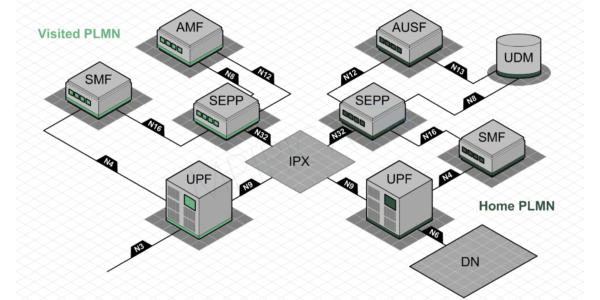
In terms of both the control and user planes, the home and visited networks are linked via the IPX (IP eXchange) in a similar way to that of LTE. However, in the case of 5G, a SEPP (Security Edge Protection Proxy) is now positioned on the edge of each network in order to provide boarder protection such as message filtering, policing and topology hiding. SEPPs therefore connect over the IPX using the N32 reference point and provide a “gateway” through which the network functions in both the home and visited networks can exchange information.
In terms of the user plane, the “intermediate” UPF (User Plane Function) in the visited network links to the “anchor” UPF in the home network using N9 which also spans the IPX. Here, GTP-U (GPRS Tunnelling Protocol – User) is used to carry user plane traffic between the two networks.
We shall return to N32 and N9 next month in Part 2 when we delve deeper into how both of these connections can be secured across the IPX. However, before that, let us take this opportunity to look into another enhancement introduced in 5G to improve roaming security.
Authentication
Like that of 3G and 4G before, 5G also support mutual authentication in which the network authenticates the subscriber and the subscriber authenticates the network, i.e. it determines whether the network it is communicating with has access to a valid authentication vector generated in its home network. However, 5G adds an additional authentication capability pertinent to roaming; in that authentication now takes place between the visited network and the home network. That is, the visited network has to prove to the home network that it has an active connection with the subscriber.
This is achieved by adding the “Serving Network Name” into a KDF (Key Derivation Function) at both the UDM (Unified Data Management) in the home network and the device itself (Figure 2). As such, this ensures that for authentication to be successful, the visited network requesting authentication vectors from the home network must be the same network that the device is actually connected to during the authentication procedure.
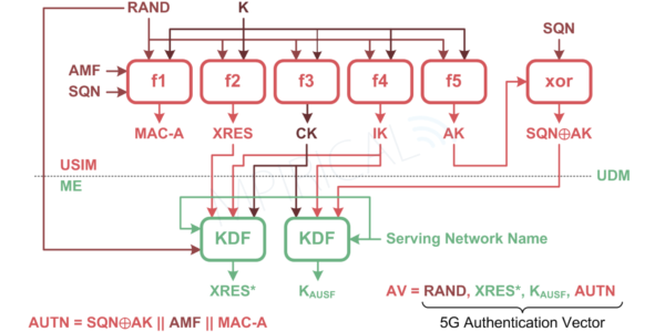
The authentication procedure therefore begins with the AMF (Access and Mobility Management Function) in the visited network requesting authentication parameters from the AUSF (Authentication Server Function) in the home network. This is passed through the SEPPs on the edge of each of the core networks. At the AUSF, the Serving Network Name of the requesting network (visited network) will be added to the request prior to sending to the UDM which will incorporate it during the generation of the 5G HE (Home Environment) Authentication Vector (Figure 2). This is passed back to the AUSF which in turn converts XRES* into HXRES* by passing it and RAND through a SHA (Secure Hashing Algorithm). The AUSF will then take HXRES*, RAND and AUTN, now known as the 5G SE (Serving Environment) Authentication Vector and will pass it to the AMF in the visited network, once again via the SEPPs.
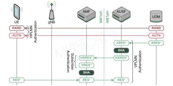
The AMF will now be able to trigger the authentication procedure towards the device by sending it the RAND and AUTN and retaining HXRES*.
The device is able to take these parameters and feed them into the “f algorithms” on the USIM and in so doing, verify that it is indeed communicating with a network that is connected to its home network. Furthermore, using the same Key Derivation Function, the device is also able to generate RES* which it returns to the AMF in the authentication response. Upon receiving this, the AMF passes RES* and RAND through the same Secure Hashing Algorithm as the AUSF and in so doing, generate HRES*. This is compared to the HXRES* which was received from the AUSF and if the same, the subscriber will be considered authenticated. Finally, the AMF will pass RES* to the AUSF in the home network which is now able to compare it to XRES* that it received from the UDM. Should these be the same then the home network can confirm that the visited network (AMF) has an active connection with one of their subscribers.
Key Distribution
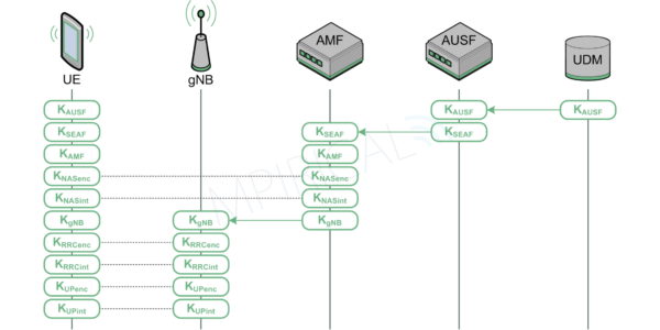
Following authentication, the next stage in the security establishment phase is key distribution which is illustrated in Figure 4. Note, this is a simplified representation and omits a number of inputs into the various Key Derivation Functions.
During the authentication procedure, KAUSF is passed to the AUSF as part of the 5G HE Authentication Vector. Here it is converted into KSEAF and passed down to the AMF in the visited network once it has been able to confirm that it is in actual communication with the device.
The AMF, it is then able to generate KAMF, KNASenc KNASint along with KgNB. KNASenc and KNASint are used to secure the NAS (Non Access Stratum) where as KgNB is passed down to the E-UTRAN. Finally, the gNB is able to generate the remaining security keys in order to protect the RRC (Radio Resource Control) signalling connection and the user plane – KRRCenc, KRRCint, KUPenc and KUPint. Note, these keys will also be generated on the device.
With these various keys in place, it is now possible to secure NAS signalling between the device and the AMF, RRC signalling between the device and the gNB and finally user plane traffic also between the device and the gNB. Furthermore, the visited network will have also probably established an IPSec (IP Security) connection between the gNB and its core network further protecting control and user plane information.
However, in terms of roaming, it is still necessary to secure both the control and user planes between the visited and home network. We shall cover this next month when we turn our attention to PRINS (Protocol for N32 Interconnect Security) and IPUPS (Inter PLMN User Plane Security).
If you would like to learn more about 5G, our expert instructors provide live classroom and on-demand 5G Security course.